/prod01/prodbucket01/media/durham-university/departments-/physics/teaching-labs/VT2A9034-1998X733.jpeg)
Overview
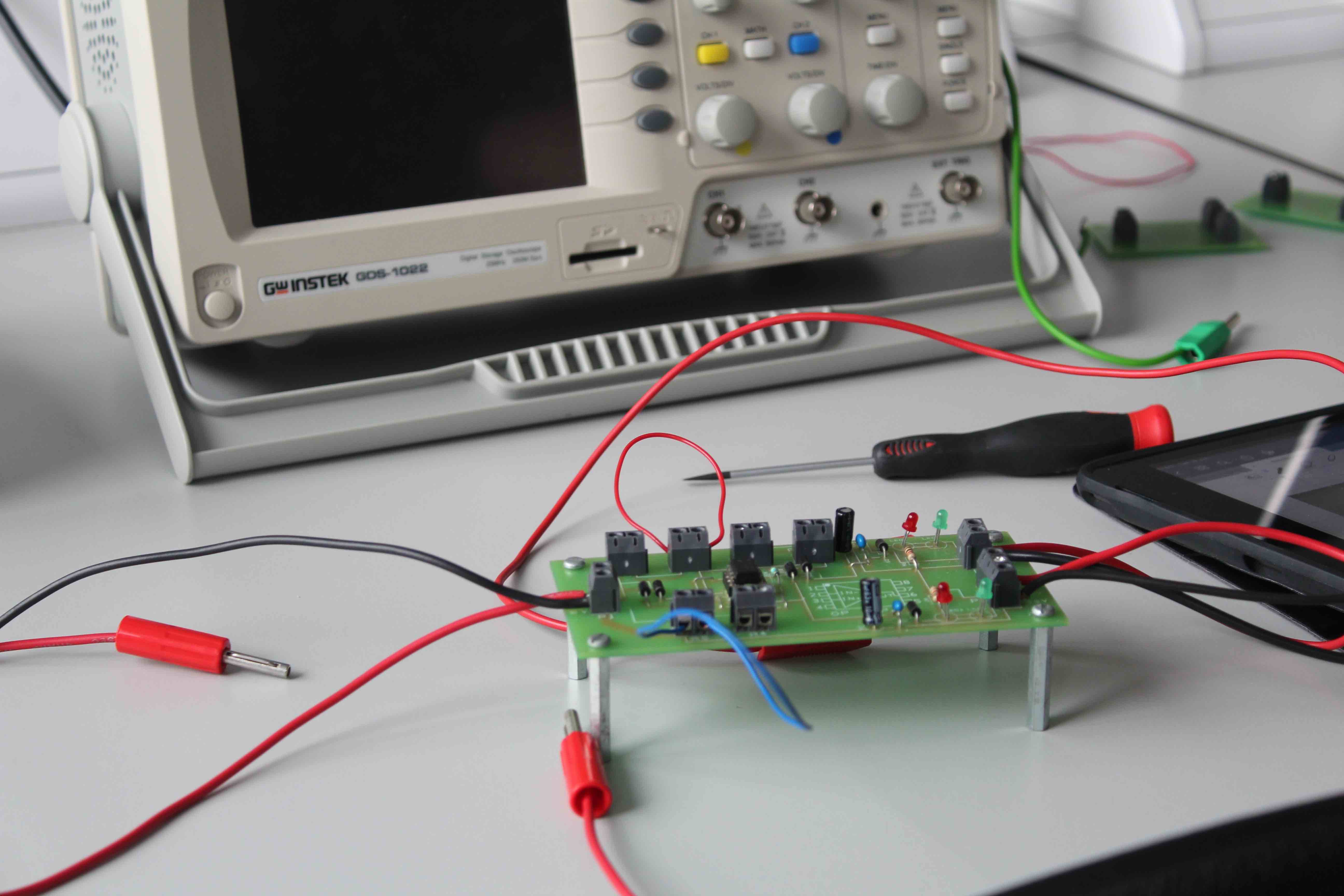
The electronics laboratories take place at the end of the Michaelmas term and the beginning of the Epiphany term. The laboratories are supported by a lecture series that explains the necessary theory and components before you undertaken each lab session. This module is assessed in a practical setting as you must complete a set of tasks individually in the laboratory. Current students can access the lab scripts via Learn Ultra.
Laboratory Sessions
You will be given instructions on proper handling of equipment, and all the electronic signals you will be processing in these sessions will be low voltage. If needed, here are links to information on basic circuits and experimental skills:
- Use of a multimeter
- Reading resistors
- Reading capacitors
- Using a waveform generator
Example circuits from this course are:
- Filters: A potential divider is a simple circuit that uses passive components to produce an output voltage that is a fraction of the input voltage. The passive components may be resistive, capacitative, inductive or some mixture of all three. The use of non-resistive components introduces a frequency dependence into the fraction filter. Frequency filters are used to modify or remove unwanted frequencies, such as noise in measurements, and have useful applications in radio tuning.
- Operational Amplifiers: You will construct and characterise several operational amplifier circuits and conduct several experiments which illustrate some of their limitations and applications as circuits, such as amplifiers. Op-amps are also widely used in IoT home devices and measuring instruments, such as temperature sensors.
- Modulation: You will investigate ways in which a signal may be modulated. Each task requires two input signals, one generated by your function generator, the other is distributed around the lab. Modulation is generally used to transfer signals through noisy environments and has been key to transmitting AM and FM radio broadcasts.
Practical Assessment:
You will only attend one of two sessions, which will be your assessment for the Electronics module.
The assessment is open book, but you will be working alone. The aim is to use the skills you have acquired in the previous sessions to detect a mystery signal.
/prod01/prodbucket01/media/durham-university/departments-/physics/labs/Electronics---3.jpeg)
/prod01/prodbucket01/media/durham-university/departments-/physics/labs/Electronics---4.jpg)
/prod01/prodbucket01/media/durham-university/departments-/physics/labs/Electronics---5.jpg)
/prod01/prodbucket01/media/durham-university/departments-/physics/labs/Electronics---1-1.jpg)