/prod01/prodbucket01/media/durham-university/departments-/physics/teaching-labs/VT2A9034-1998X733.jpeg)
Circuits
Many of the labs you take part in this year will require basic understanding of electrical circuits and their components. You have a chance to practise these skills in the Circuits 1 and Circuits 2 lab skill sessions.
You will need to be familiar with:
Other resources:
- The Art of Electronics, Horowitz and Hill
- University of Guelph Circuits Tutorial
- Virtual Circuits
Ohm's Law
Ohm's Law defines the relationships between power, voltage, current, and resistance.
The direct current flowing in a conductor is directly proportional to the potential difference between its ends; or one ohm is the resistance through which one volt will maintain a current of one ampere.
This is usually formulated as V=IR. Power, P, is given by P = IV.
- Current, I, is what flows in a conductor like water flowing down a river. Current flows from points of high voltage to points of low voltage. Current is measured in amperes (amps), an SI base unit.
- Voltage, V, is the difference in electrical potential between two points in a circuit. A potential difference is usually required to keep current flowing through a circuit and is measured in volts, the conventional symbol for which is also V and is equivalent to W A-1.
- Resistance, R, determines how much current will flow through a component. Resistors are used to control voltage and current levels. A very high resistance allows a small amount of current to flow. A very low resistance allows a large amount of current to flow. Resistance is measured in ohms, equivalent to V A-1.
- Power, P, is the rate of energy dissipation in a circuit between two points. Its value is the voltage drop between the points multiplied by the current flowing between those two points. Power is measured in watts.
(Adapted from here.)
Kirchhoff's Laws
Kirchhoff's Laws allows us to analyse more complex circuits, which are not composed exclusively of parallel or series components. Kirchhoff's Laws apply to DC circuits and to networks.
-
Kirchhoff's Current Law: At any instant the sum of all the currents flowing into any circuit node is equal to the sum of all the currents flowing out of that node. Similarly, at any instant the algebraic sum of all the currents at any circuit node is zero.This is saying that charge is conserved.
-
Kirchhoff's Voltage Law: At any instant the sum of all the voltage sources in any closed circuit is equal to the sum of all the voltage drops in that circuit. Similarly, at any instant the algebraic sum of all the voltages around any closed circuit is zero. This is saying that energy is conserved.
Other resources:
Resistors
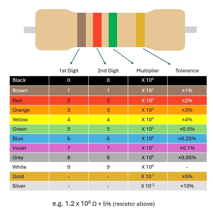
The resistance of a resistor is marked using colour band codes, as shown in figure 1. The table below shows what number each colour represents. To read the resistor, look up the 1st and 2nd digit and then add the number of zeros given by the multiplier band.
For the resistor shown, the first digit is a 1 (brown), the second digit is a 2 (red) and the multiplier is a 5 (green), so the nominal resistance is 1.2 MΩ. Its tolerance is 5% (gold) so the expected value of the resistor is 1.2±0.06 MΩ.
A much more accurate value could be determined using a multimeter. The resistor in figure 1 was measured to have a real resistance of 1.15±0.1 MΩ - in excellent agreement with the expected value.
Sometimes a resistor will have an extra band. In that case, the first three bands represent digits and the fourth is the multiplier. For example, if the there was an extra green band after the 1st and 2nd digits, the expected resistance would be 1.25 ± 0.063 MΩ.
All the colours are given with their values in the table below.
Fig 1. Resistor colour bands.
Resistors remove energy from a circuit in the form of heat. The ability of a resistor to move this heat to the environment is given by its power rating. The standard power ratings available are 0.25W and 0.5W which should be sufficient for most purposes.
Capacitors
Capacitors are devices that temporarily store electrical charge or energy in an electrical field between two oppositely charged plates. The most basic capacitor design consists of two separated conducting plates. Many practical capacitors have a dielectric between several layers of plates to increase their capacitance. The charge is stored at the surface of the plates, at the boundary with the dielectric.
Capacitance is defined as the amount of charge stored on the plates for a given potential difference between them (C = Q/V). The basic unit of capacitance is the farad (F), although more commonly used is the microfarad (μF) or even the nanofarad (nF).
- Capacitors In Series: The inverse of the total capacitance of a number of capacitors in series is the sum of the reciprocals of the individual capacitances.
- Capacitors In Parallel:The total capacitance of capacitors in parallel is the sum of the individual capacitances.
Other resources:
Inductors
Inductance is the behaviour whereby a coil of wire resists a change in the electric current passing through it by generating an emf (ξ). The change in current produces a time varying magnetic field which in turn produces the emf. The Inductance (L) of a coil is defined by:
 , (6)
, (6)Where dI/dt is the rate of change of current I. The unit of inductance is the henry, or volt seconds per ampere.
All wires have inductive properties which vary with frequency, but when we talk about an inductor as a component we usually mean a coil as they can have a significant inductance at low frequencies. Note that a coil that provides a high inductance does not necessarily provide a high resistance.
LR circuits contain an inductor, a resistor and power supply that produces a time varying output (eg. a function generator). Due to the high frequency of the current, the interconnecting wires tend to have a capacitance and so we can only ever build LCR circuits, ie. those which contain a capacitor.
Other resources:
Potential dividers, or voltage dividers, are used to split the current and voltage in a circuit so that parts of the circuit only receive the current and voltage they require. Potential dividers may use variable or fixed resistors.