/prod01/prodbucket01/media/durham-university/departments-/physics/teaching-labs/VT2A9034-1998X733.jpeg)
Digital Multimeters
Introduction
Digital multimeters can be used to measure a number of different properties of an electrical circuit including voltage, current and resistance. A level 1 multimeter is shown in the figures below.
Use as an ammeter
To use the multimeter as an ammeter (i.e. to measure the current) follow the steps below:
- Connect the black lead to the "COM" (Common Input Jack) port on the multimeter.
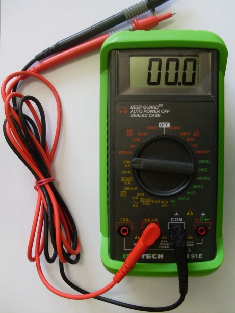
- For current measurements up to 200 mA, connect the red lead to the "mA μA" port, shown in Fig.2.
- For currents between 200 mA and 10 A, connect the red lead to the "10 A" port.
- Connect the other ends of the leads in series with the circuit you wish to measure the current across. When the multimeter is in this setting it is in a extremely low resistance setting, so it must be connected in series.
- Adjust the dial to the correct range of current for your circuit. These are yellow on the multimeter shown in the figures below. If you are unsure of what sort of range your current lies, go for a high current and work downwards.
Use as a voltmeter
To use the multimeter as a voltmeter, follow the steps below:
- Connect the black lead to the "COM" (Common Input Jack) port on the multimeter.
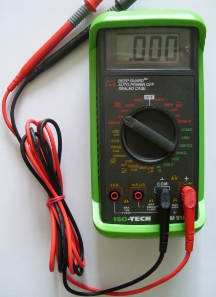
- Connect the red lead to the "V Ω" port, shown in Fig.2.
- Connect the other ends of the leads in parallel to the part of the circuit you wish to measure the potential difference of. This is because the multimeter will have a very high resistance setting.
- Adjust the dial to the correct range of voltages for your circuit. Note that if your circuit is DC (Direct Current) then make sure you select voltages from the left of the dial. Similarly, if your circuit is AC (Alternating Current) then make sure you select voltages from the right of the dial.
- If you are unsure on what range your voltage lies, start high and then work downwards.
Use as an ohmmeter
To use the multimeter as a ohmmeter, follow the steps below.
- Set up the multimeter as shown Fig.2 (i.e. black lead in COM port, red lead in "V Ω" port).
- Disconnect the component you want to measure the resistance of from the rest of the circuit. The reason for this is that the multimeter needs to apply its own test current across the device to measure the resistance.
- Connect the multimeter across the terminals of the device.
- Set the dial to the resistance range you want to measure, shown in green in the figures. If you are unsure about what range you think the resistance lies, start high and then work down.
 |
 |
|---|---|
| Figure 1: A digital multimeter in a setting suitable to measure small currents | Figure 2: A digital multimeter in a setting suitable to measure voltages |